Sim/circuit1
从波形不难看出ab是相与的关系。
module top_module (
    input a,
    input b,
    output q );//

    assign q = a&b; // Fix me
endmodule
Sim/circuit2

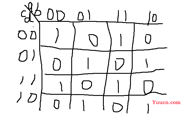
根据波形图可以画出卡诺图并且之前有写过这个卡诺图的逻辑表达式,不难看出相邻逻辑输出会取反,所以这个是一个四变量的异或,0000输出为1,所以还要再取反。
module top_module (
    input a,
    input b,
    input c,
    input d,
    output q );//

    assign q = ~(a^b^c^d); // Fix me
endmodule
Sim/circuit3
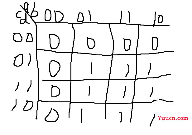
继续画卡诺图

module top_module (
    input a,
    input b,
    input c,
    input d,
    output q );//

    assign q = (b&d)||(a&d)||(b&c)||(a&c); // Fix me
endmodule
Sim/circuit4
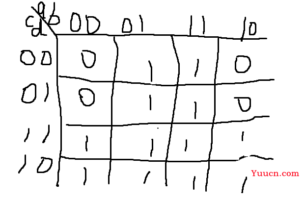
还是画卡诺图,把四个0的位置确定好就行。

module top_module (
    input a,
    input b,
    input c,
    input d,
    output q );//

    assign q = b|c; // Fix me
endmodule
Sim/circuit5
显然这是一个数据选择器,c的0123分别选择bead,c为别的值的时候输出值为f。
module top_module (
    input [3:0] a,
    input [3:0] b,
    input [3:0] c,
    input [3:0] d,
    input [3:0] e,
    output [3:0] q );
    always@(*)
    begin
           q=4'hf;
        case(c)
            0:q=b;
            1:q=e;
            2:q=a;
            3:q=d;
        endcase
    end
endmodule
Sim/circuit6
暴力强解。
module top_module (
    input [2:0] a,
    output [15:0] q );
    always@(*)
    begin
        case(a)
            0:q=16'h1232;
            1:q=16'haee0;
            2:q=16'h27d4;
            3:q=16'h5a0e;
            4:q=16'h2066;
            5:q=16'h64ce;
            6:q=16'hc526;
            7:q=16'h2f19;
            default:q=0;
        endcase
    end
endmodule
Sim/circuit7
由图中不难看出来q是对a的取反,采取时序逻辑恰好延后了一个周期。
module top_module (
    input clk,
    input a,
    output reg q );
    always@(posedge clk)
    begin
        q <= ~a;
    end
endmodule
Sim/circuit8
从波形图不难看出p在clock高电平时改变,低电平锁存,所以是一个锁存器。q在时钟下降沿发生变化,是一个下降沿触发的触发器。
module top_module (
    input clock,
    input a,
    output reg p,
    output reg q );
    always@(*)
    begin
        if(clock)
            p = a;
    end
    always@(negedge clock)
    begin
        q <= a;
    end
endmodule
Sim/circuit9
该电路在a为低电平时计数,高电平置为4,并且计数最多到6就清零。
module top_module (
    input clk,
    input a,
    output [3:0] q );
    always@(posedge clk)
    begin
        if(~a)
            q <= (q<6)?(q+1):0;
        else
            q <= 4;
    end
endmodule
Sim/circuit10
仔细看波形图,状态在ab同为1跳转为1,ab同为0跳转为0。
分别观察两个状态的逻辑,发现恰好一个是异或一个异或非。
module top_module (
    input clk,
    input a,
    input b,
    output q,
    output reg state  );
    parameter A=0,B=1;
    reg next_state;
    always@(posedge clk)
    begin
        state <= next_state;
    end
    always@(*)
    begin
        if(a&b)
            next_state <= B;
        else if(~(a|b))
            next_state <= A;
    end
    assign q=state?~(a^b):(a^b);
endmodule